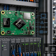
What Is a Carrier Board in Embedded Computing?
When developing an embedded product, selecting the right processor or System on Module (SoM) is only one part of the hardware design process. The computing module delivers the system’s core processing capabilities, but it also needs connections to displays, cameras, sensors, storage, communication networks, and other peripherals.
That is where a carrier board plays a role.
A carrier board is a standard or custom PCB that hosts an embedded computing module and connects it to the rest of the product. It supplies the physical interfaces, power circuitry, and application-specific hardware required to turn the module into a complete embedded system.
Carrier boards are common in industrial computers, robotics, AI edge devices, smart terminals, and many other embedded applications. Understanding their function can help manufacturers make informed choices about hardware architecture, development costs, and product customization.
1. What Is a Carrier Board?
A carrier board, also known as a baseboard or breakout board, is a printed circuit board that links a System on Module (SoM) or Computer-on-Module (CoM) with external hardware.
An embedded computing system built around this design typically has two primary components:
- SoM: Houses the essential computing elements, including the processor, RAM, storage, and power-management circuitry.
- Carrier Board: Supplies the connectors, power input, peripheral interfaces, and application-specific circuitry required by the final product.
- The boards exchange signals through a board-to-board connector, an edge connector, or another established electrical interface.
For instance, an embedded SoM might offer signals for USB, Ethernet, display output, camera input, UART, and GPIO. The carrier board directs the necessary signals to physical connectors and includes the circuitry required to interface with external devices.
Rather than developing a complete computing platform from the ground up, manufacturers can adopt an existing SoM and focus their hardware design work on the carrier board.
2. How Does a Carrier Board Work?
A carrier board serves as the connection layer between an embedded product’s computing module and its external components.
The SoM performs the primary computing work, while the carrier board adapts the module for use in a particular application.
A typical system operates as follows:
Step 1: The SoM carries out computing tasks
The processor runs the operating system and application software. Memory and storage support system operation, while integrated graphics and AI acceleration manage supported workloads.
Step 2: The module connects to the carrier board
The SoM is mounted using a compatible high-density connector or another module interface. Power and signals pass between the two boards.
Step 3: The carrier board provides external connections
The carrier board routes required signals to connectors and peripheral circuits, enabling the computing module to communicate with external hardware.
Step 4: The complete system functions as an embedded product
After the display, cameras, sensors, network interfaces, and other peripherals are connected, the combined hardware can operate in its intended device.
For example, an industrial HMI may use an SoM to process applications and render displays, while its carrier board supplies the touchscreen connection, Ethernet, RS485, USB, and power input.
3. What Is the Role of a Carrier Board?
Although its design varies according to the application, most carrier boards carry out several essential functions.
Power Management
A carrier board typically accepts the system’s power input and distributes it to the computing module and attached peripherals.
Depending on the design, it may provide:
- DC power input
- Voltage regulation and conversion
- Power distribution circuitry
- Power sequencing and protection
- Battery charging or monitoring circuitry, as needed
The power design must accommodate the module’s input specifications, peripheral loads, startup current, and operating conditions.
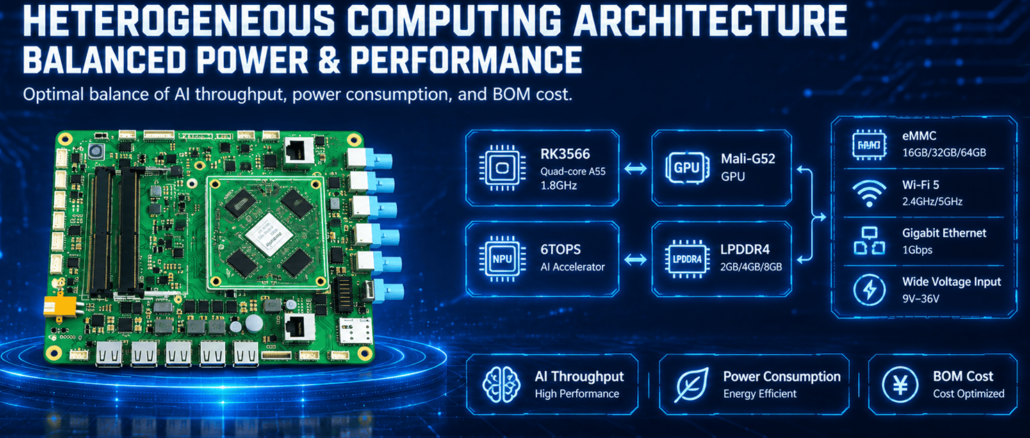
rk3588 carried board
Interface Expansion
A carrier board’s primary roles include making the interfaces required by the finished product available.
Common connections include:
| Interface | Typical application |
|---|---|
| USB | Touchscreens, storage, keyboards, peripherals |
| Ethernet | Network communication and industrial connectivity |
| HDMI / eDP | Display connection |
| MIPI DSI | Embedded LCD panels |
| MIPI CSI | Camera modules |
| RS485 / RS232 | Industrial equipment communication |
| CAN / CAN FD | Automotive and industrial control |
| GPIO | Sensors, switches, and control signals |
| I2C / SPI / UART | Peripheral and device communication |
Not all SoMs provide every interface, and an available signal does not necessarily need to be connected to an external connector. The carrier board determines which supported signals are put to use.
Peripheral Integration
Many embedded products require additional hardware beyond the basic connectors.
A carrier board can incorporate:
- Ethernet PHYs and network connectors
- RS485 or CAN transceivers
- Audio amplifiers and microphone circuits
- Camera connectors
- Touchscreen interfaces
- Sensor connectors
- Wireless communication modules
- Expansion slots and storage interfaces
This flexibility enables one computing module to support different products when paired with appropriately designed carrier boards.
Mechanical Integration
A carrier board also helps tailor the computing module to the physical design of the finished product.
Its PCB dimensions, connector locations, mounting holes, and component layout can be customized to fit the enclosure.
In compact products such as smart control panels and robotics equipment, mechanical integration is especially important. Space constraints, cable routing, and thermal management can all have a direct impact on the design.
4. Carrier Board vs. SoM: What Is the Difference?
Although these two boards work together, they have different responsibilities.
| Comparison | System on Module (SoM) | Carrier Board |
|---|---|---|
| Main role | Core computing | System integration |
| Main components | Processor, RAM, storage, PMIC | Connectors, power circuits, peripheral components |
| Design focus | Computing performance and system stability | Interfaces, power, and application requirements |
| Customization | Processor and memory platform options | Product-specific hardware and connections |
| Reusability | Can be reused across compatible designs | Usually designed for a specific product or product family |
| Replacement | Can be upgraded within a compatible platform | May need modification when module interfaces change |
The distinction is easiest to understand this way:
The SoM delivers computing capabilities, while the carrier board connects those capabilities to the product.
A SoM is not always a complete, standalone computer. Many embedded systems require a compatible carrier board to supply power and provide external connections.
This modular design keeps the complex computing architecture separate from application-specific hardware development.
5. Carrier Board vs. Custom Motherboard
Although a carrier board and a custom motherboard are related, they are not the same.
A carrier board is built to work with an existing computing module. The processor and other essential computing components are already integrated into the SoM.
A custom motherboard may place the processor, memory, storage, power management, connectors, and peripheral circuits directly on a single PCB.
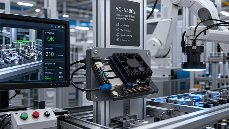
NVIDIA Jetson Orin NX/Nano AI Edge Computing Carrier Board
Here are the main differences:
| Factor | Carrier Board + SoM | Custom Motherboard |
|---|---|---|
| Architecture | Two-board modular design | Integrated single-board design |
| Processor design | Provided by the SoM | Designed into the motherboard |
| High-speed memory routing | Primarily handled on the SoM | Requires motherboard-level design |
| Hardware customization | Focuses on I/O and peripherals | Can cover the entire hardware platform |
| Development complexity | Often lower for the computing subsystem | Generally higher |
| Upgrade flexibility | Depends on module compatibility | Usually requires a board redesign |
| Product integration | Requires module and carrier assembly | More integrated hardware structure |
A carrier-board architecture can reduce the high-speed processor and memory design work required for a project, but it does not remove the need for engineering validation. Developers must still verify power delivery, signal routing, thermal performance, electromagnetic compatibility, and software integration.
For products with specialized dimensions or connectors, or those intended for high-volume production, a custom motherboard may offer a better long-term solution.
6. Why Choose a Custom Carrier Board?
A standard development carrier board is useful in early prototyping, providing a ready-made environment for testing a computing module.
However, development boards often include more interfaces than a commercial product requires.
A custom carrier board enables manufacturers to design hardware around a product’s specific requirements.
Application-Specific Interfaces
An industrial controller may need RS485, CAN FD, multiple GPIO connections, and Ethernet. A smart display may instead prioritize HDMI, MIPI DSI, USB, audio, and touchscreen connectivity.
A custom carrier board can offer the right combination of interfaces without adding unnecessary connectors.
Smaller Product Dimensions
Standard development boards are built for general-purpose evaluation and may not fit the mechanical constraints of a compact commercial product.
A custom PCB can optimize component placement, connector locations, and mounting points to fit the intended enclosure.
Improved Peripheral Integration
A project may need dedicated camera connectors, sensor interfaces, wireless modules, or industrial communication circuits.
Integrating these components directly into the carrier board can streamline wiring and system assembly.
More Efficient Production Design
A custom carrier board can eliminate unnecessary development-board components and tailor the hardware to the final production structure.
For manufacturers planning long-term production, this approach can increase assembly efficiency and support a more consistent product configuration.
7. Designing a Carrier Board for an Embedded Product
Carrier-board development requires close coordination among hardware, software, and mechanical engineering teams.
Before beginning the PCB layout, manufacturers should define the system requirements.
1. Choose a Compatible SoM
Identify the processor platform, memory configuration, operating system, module dimensions, connector type, and available signals.
Review the module’s pinout and hardware design documentation before starting carrier-board development.
2. Define the required interfaces
Compile a complete inventory of external connections.
Consider:
- Display resolution and interface
- Touchscreen communication
- Number of cameras and required bandwidth
- Ethernet speed and number of ports
- USB requirements
- RS485, RS232, and CAN communication
- GPIO and sensor connections
- Storage and expansion requirements
This process helps prevent unnecessary hardware and reduces the risk of overlooking essential connections.
3. Design the power system
Calculate the power requirements for the SoM and every connected peripheral.
Account for input voltage, voltage conversion, peak current, startup behavior, power sequencing, and protection circuits.
4. Complete the schematic and PCB design
The hardware design should account for connector placement, signal integrity, impedance-controlled routing, grounding, electromagnetic compatibility, and thermal management.
High-speed interfaces, including USB 3.0, PCIe, MIPI, and high-resolution display connections, require special attention.
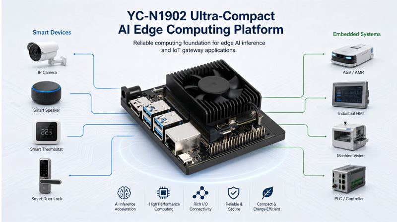
NVIDIA Jetson Orin NX/Nano AI Edge Computing Carrier Board
5. Integrate the software and drivers
The carrier board must be compatible with the SoM’s software platform.
Depending on the module’s BSP, developers may need to configure device trees, pin multiplexing, drivers, interface settings, and power-management functions.
A peripheral’s physical connection alone does not guarantee that it will work; the required software support must also be available.
6. Prototype and validate
Before mass production, test the complete system in both hardware and software.
Key validation items include:
- Power stability and startup behavior
- Display and touchscreen operation
- Ethernet and peripheral communication
- Camera functionality
- Thermal performance
- Signal integrity
- EMC pre-compliance testing
- Long-duration operating stability
Testing the complete system is essential, as the carrier board can affect the embedded product’s overall performance and reliability.
8. Carrier Board Applications in Embedded Computing
Carrier boards are valuable in applications where a computing module must be tailored to a specific device.
Industrial HMI Systems
Industrial HMI products may require LCD connectivity, touch interfaces, Ethernet, RS485, USB, and dedicated control signals.
A custom carrier board can bring these connections together on a compact PCB designed to fit the machine enclosure and withstand its operating conditions.
Robotics and Autonomous Equipment
Robotic platforms commonly integrate cameras, sensors, network connections, motor controllers, and user interfaces.
A carrier board can link the computing module with these subsystems and provide the necessary power and communication interfaces.
In complex robotics applications, the main computing module may perform perception and application processing, while dedicated controllers handle real-time motor operation and safety-critical functions.
AI Edge Computing Devices
AI edge devices may require camera inputs, high-speed storage, Ethernet, wireless connectivity, and display outputs.
A carrier board can be designed for the selected SoM to support the necessary cameras, network connections, and expansion hardware.
Smart Home Control Panels
Smart home control panels may integrate a touchscreen, Ethernet, Wi-Fi, Bluetooth, RS485, and other home automation interfaces.
A customized carrier board can connect the computing module to the display and communication hardware the product requires.
Digital Signage and Smart Kiosks
Commercial display systems commonly need display outputs, touchscreen interfaces, audio, network connectivity, USB peripherals, and power-management functions.
A carrier board brings these capabilities together in a product-specific hardware design for wall-mounted displays, interactive kiosks, and advertising terminals.
9. Portworld RK3576 SoM and Carrier Board Customization
Embedded manufacturers seeking a customized computing platform without designing the full processor subsystem from the ground up can use Portworld’s RK3576 System on Module.
Built around the Rockchip RK3576 octa-core processor, the Portworld RK3576 SoM integrates the core computing components in a compact module.

NVIDIA Jetson Orin Carrier Board for AI Edge Computing
Key specifications include:
Rockchip RK3576 octa-core processor
4 × Cortex-A72 cores running at up to 2.2GHz and 4 × Cortex-A53 cores running at up to 1.8GHz
Mali-G52 MC3 GPU
Integrated NPU delivering up to 6 TOPS INT8 performance under supported sparse-computing conditions
- 4GB onboard LPDDR4 memory
- Module dimensions of 38 × 38mm
- 240-pin board-to-board connector
- 16MP ISP with HDR and 3D noise reduction
Support for Linux, Ubuntu, and Android, depending on the BSP configuration
The 240-pin board-to-board connector links the SoM electrically to a compatible carrier board.
For projects using this module, the carrier board can be tailored to the required display, network, storage, camera, and industrial communication interfaces.
For example:
- An industrial HMI project may need MIPI DSI, touch input, Ethernet, and RS485.
- A robotics project may prioritize camera connections, USB, Ethernet, UART, and CAN FD.
- An AI edge device may require camera interfaces, high-speed storage, and network connectivity.
- The actual interfaces available on the finished system depend on the SoM pinout, carrier-board design, component selection, and BSP support.
In addition to the RK3576 SoM, Portworld offers the P3576 Smart Mainboard for projects that prefer a more integrated board-level solution rather than a separate SoM and custom carrier-board architecture.
Portworld’s engineering services can support PCB and PCBA design, hardware customization, operating-system adaptation, peripheral integration, and OEM/ODM development.