How Is a Smart Home Control Panel PCBA Manufactured?
Understanding the Manufacturing Process Behind Smart Home Control Panels
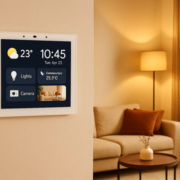
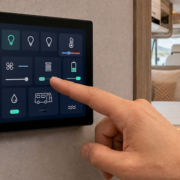
Smart home control panels have emerged as a fundamental element within contemporary home automation systems. These touchscreen devices function as a primary hub for managing:
- Smart lighting
- HVAC systems
- Motorized curtains
- Security devices
- IoT sensors
- Smart appliances
Beneath the touchscreen interface and refined exterior housing resides a vital electronic component — the PCBA (Printed Circuit Board Assembly).
The PCBA serves as the foundational hardware infrastructure that integrates the processor, communication modules, display, touch controller, power system, and external interfaces into a unified system.
Accordingly, what is the methodology employed in manufacturing a smart home control panel PCBA?
The manufacturing process encompasses several sequential phases, including PCB design, component procurement, SMT assembly, firmware installation, comprehensive testing, and rigorous quality assurance inspection.
1. Smart Home Control Panel PCBA Design
The manufacturing process commences with electronic design.
Engineers establish the hardware architecture in accordance with product specifications.
A standard smart control panel PCBA comprises:
Primary Components:
- Processor / MCU
- Accountable for system functionality.
Typical Examples:
- Rockchip processors utilized in Android smart panels
- ESP32 series microcontrollers employed in IoT control panels
- ARM-based embedded processing units
Operational Functions:
- Execution of the operating system
- Interpretation of touch interface commands
- Administration of communication protocols
- Memory Components
Comprising:
- Random Access Memory (RAM)
- Flash storage capacity
- Electrically Erasable Programmable Read-Only Memory (EEPROM)
Applications:
- Operating system files
- Software applications
- User configuration settings
- Firmware retention
Communication Modules
Intelligent home control panels necessitate multiple communication connectivity solutions.
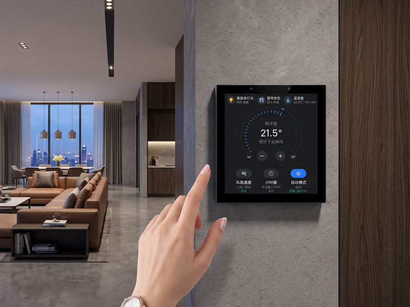
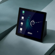
Smart Home Touch Control Panel
Standard modules encompass:
- WiFi
- Bluetooth
- Zigbee
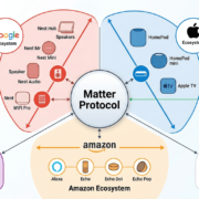
- Thread/Matter
- Ethernet
- RS485
These facilitate interaction with intelligent devices and control system infrastructure.
Power Management Circuit
The PCBA incorporates power management circuitry that transforms input electrical power into regulated voltage levels.
Acceptable power supply options may encompass:
- Direct current power input
- USB Type-C connectivity
- Power over Ethernet (PoE)
Power management circuits guarantee dependable functionality of:
- Central processor
- Display unit
- Touchscreen interface
- Communication modules
2. PCB Layout and Engineering
Following circuit design completion, engineering professionals develop the PCB layout configuration.
The layout configuration establishes:
- Positioning of components
- Electrical signal pathways
- Electrical power allocation
- Thermal regulation strategies
For intelligent control panel applications, PCB design must address:
High-Speed Signal Management
Including:
- Display connection interfaces
- Ethernet data transmission
- Memory access signals
Radio Frequency Design
Wireless communication modules demand meticulous antenna engineering.
Critical design considerations:
- Radio signal transmission strength
- Electromagnetic interference mitigation
- Consistent wireless performance
Industrial Communication Interfaces
Advanced smart control panels may incorporate:
- RS485 serial communication
- Relay switching interfaces
- General-purpose input/output ports
- Universal Serial Bus connectivity
- Ethernet network interfaces
The PCB must be engineered to guarantee consistent operational performance.
3. PCB Fabrication
Following the completion of PCB design, PCB manufacturers proceed to fabricate the bare circuit board.
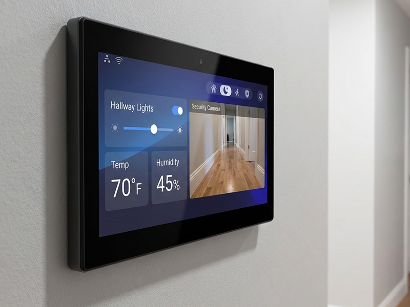
smart home control panel-1
The manufacturing process encompasses:
Copper Layer Manufacturing
Electrical connections are established through the creation of copper layers.
Drilling
Precision holes are drilled to facilitate:
- Component mounting
- Electrical connections
- Solder Mask Application
A protective coating is applied to mitigate the risk of short circuits.
Surface Finishing
Standard finishing techniques include:
- HASL
- ENIG
These methods enhance solder joint reliability and durability.
4. SMT Assembly Process
The subsequent phase involves Surface Mount Technology (SMT) assembly operations.
During SMT manufacturing, electronic components are positioned automatically onto the PCB substrate.
The assembly process comprises:
Step 1: Solder Paste Printing
A stencil printing apparatus deposits solder paste onto designated PCB pads.
Following thermal processing, the solder paste establishes electrical connections between components.
Step 2: Component Placement
Automated high-speed placement equipment installs components with precision.
Components being installed include:
- Integrated circuit chips
- Resistive elements
- Capacitive elements
- Memory storage chips
- Communication interface modules
Step 3: Reflow Soldering
The assembled PCB undergoes processing through a reflow oven.
During this process, the solder paste liquefies and establishes permanent connections between components.
Step 4: AOI Inspection
Automated Optical Inspection performs verification of:
- Absent components
- Improper component positioning
- Solder quality issues
5. DIP Assembly and Supplementary Components
Certain components are incompatible with SMT assembly methods.
Typical examples include:
- Bulky connectors
- Ethernet interfaces
- Terminal blocks
- Relay devices
These applications may necessitate:
- Through-hole assembly techniques
- Manual soldering procedures
6. Firmware Programming
Following the completion of hardware assembly, firmware is installed onto the PCBA.
The firmware manages:
- Initialization of hardware systems
- Communication protocol implementation
- Touchscreen functionality
- Device operational control
For intelligent home automation panels, firmware implementations may incorporate:
- Android operating system
- Linux operating system
- FreeRTOS real-time operating system
- LVGL graphical interface libraries
7. Functional Testing
All intelligent control panel printed circuit board assemblies are required to undergo comprehensive electrical and functional testing procedures.
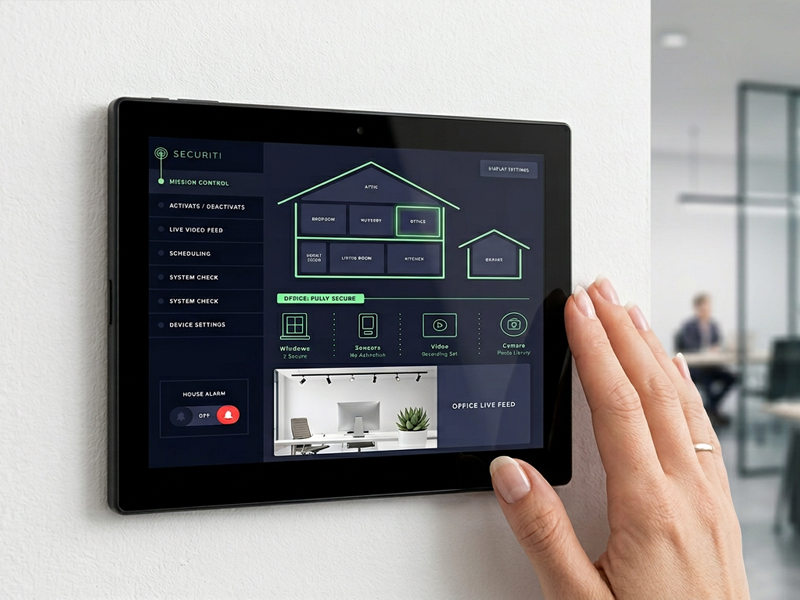
smart home control panel
The testing protocol encompasses:
Power Testing
Evaluation criteria:
- Electrical voltage consistency
- Electrical current draw analysis
- Power distribution and regulation
Communication Testing
Assessment procedures:
- Wireless network connectivity
- Bluetooth protocol functionality
- Ethernet network interface
- RS485 serial communication
Display and Touch Testing
Evaluation criteria:
- Liquid crystal display performance
- Touch input precision
- Multi-touch capability verification
Interface Testing
Comprising:
- Universal serial bus functionality
- General-purpose input/output operations
- Audio output systems
- Sensor integration and performance
8. PCBA Integration With Display and Housing
Following successful PCBA testing, the circuit board is incorporated into the finished product.
The assembly process encompasses:
- LCD display connection
- Touch panel installation
- Speaker installation
- Enclosure assembly
- Wall mounting structure
The resulting device functions as a comprehensive smart home control panel.
9. Final Quality Inspection
Prior to distribution, manufacturers conduct comprehensive final inspections.
Quality assurance procedures include:
Appearance Inspection
Evaluation of:
- Housing quality
- Screen defects
- Assembly accuracy
- Software Testing
Verification of:
- Boot process
- User interface
- Application functions
- Reliability Testing
Comprising:
- Temperature testing
- Long-term operation testing
- Communication stability testing
Smart Home Control Panel PCBA Manufacturing Process
The comprehensive manufacturing procedure can be delineated as follows:
Product Requirement
↓
Hardware Design
↓
PCB Layout
↓
PCB Fabrication
↓
SMT Assembly
↓
DIP Assembly
↓
Firmware Programming
↓
Functional Testing
↓
Final Assembly
↓
Quality Inspection
↓
Mass Production
Characteristics of a Superior Smart Home Control Panel PCBA
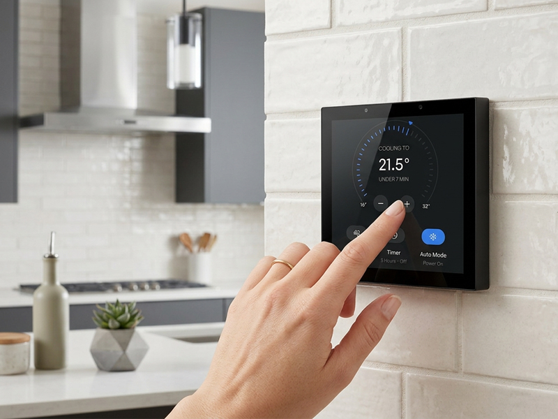
smart control panel
A dependable smart home control panel PCBA must incorporate the following essential elements:
Robust Processing Performance
To ensure seamless functionality:
- ARM-based processors
- ESP32 microcontrollers
- Embedded computing systems
- Dependable Connectivity Solutions
Capabilities encompassing:
- WiFi connectivity
- Bluetooth technology
- Zigbee protocol support
- Matter standard compatibility
- Ethernet connectivity
- RS485 serial communication
- Sound Hardware Architecture
Comprehending:
- Optimized circuit board layout
- Effective heat dissipation mechanisms
- Radio frequency signal optimization
- Safety and surge protection mechanisms
- Extensive Adaptation Options
OEM and ODM service providers have the capability to modify:
- Circuit board configuration
- Connectivity ports and interfaces
- Microprocessor specifications
- Screen dimensions and resolution
- System software and operating code
- Custom software solutions
Portworld Smart Control Panel PCBA Development
Portworld delivers tailored smart control panel solutions encompassing:
- Hardware design
- PCBA development
- Embedded software
- Touchscreen integration
- Firmware customization
- OEM/ODM production
The company’s smart panel platforms comprise:
YC-SM43P ESP32-S3 Smart Panel
Key characteristics:
- ESP32-S3 processor
- LVGL UI support
- WiFi + Bluetooth connectivity
- RS485 communication capability
- IoT-oriented architecture
Applications include:
- Smart switches
- IoT terminals
- Embedded controllers
YC-SM10P Android Smart Control Panel
Key characteristics:
- RK3566 processor
- Android operating system
- 10-inch touchscreen display
- Ethernet + PoE connectivity
- RS485 support
Applications include:
- Smart home systems
- Hospitality environments
- Office automation solutions
The production of a smart home control panel PCBA encompasses a comprehensive workflow spanning electronic design, PCB manufacturing, surface mount technology assembly, firmware installation, and rigorous quality assurance procedures.
A properly engineered PCBA delivers:
- Consistent communication with smart devices
- Fluid touchscreen functionality
- Durable extended operational reliability
- Adaptable Internet of Things connectivity