Difference between UART and RS232 protocols explained
In the world of embedded systems, industrial IoT, and smart hardware design, serial communication remains the backbone of data exchange. If you are developing a new hardware product, designing a carrier board, or integrating custom touchscreen solutions, you have undoubtedly come across the terms UART and RS232.
While they are frequently used in the same breath, they are not the same thing. Mistaking one for the other can lead to fried components, communication failures, and costly PCB redesigns.
This article breaks down the fundamental differences between UART and RS232, explains how they work together, and helps you choose the right interface for your next hardware project.
The Core Difference: Protocol vs. Physical Standard
The easiest way to understand the difference is to separate the brain from the voice.
-
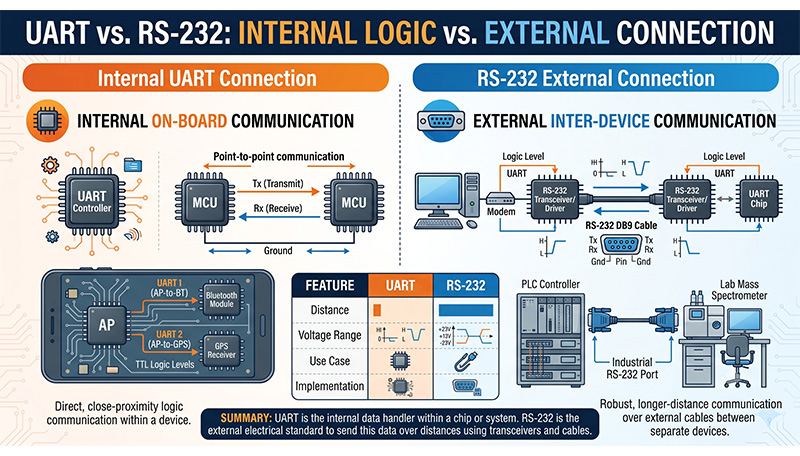
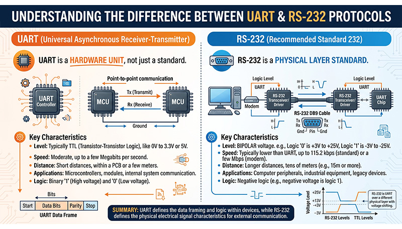
UART (Universal Asynchronous Receiver-Transmitter) is the protocol/controller (the brain). It defines how data is framed, timed, and packaged into bits.
-
RS232 (Recommended Standard 232) is the physical layer standard (the voice). It defines the electrical voltage levels, pinouts, and cabling used to transmit those bits across distances.
Analogy: Think of UART as the English language (the rules of communication) and RS232 as a megaphone (the physical medium used to make the voice travel farther).
UART and RS232 protocols
What is UART? (The Controller Layer)
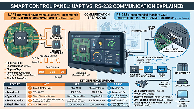
UART is a physical circuit (hardware block) integrated into microcontrollers, SoCs (like Rockchip RK3588 or RK3566), and processors. It facilitates asynchronous serial communication, meaning it does not use a shared clock signal to synchronize the transmitter and receiver. Instead, it relies on predefined baud rates (e.g., 9600, 115200 bps) and configurable data packets.
Key Characteristics of UART:
- Signal Lines: Typically uses just two wires for data: TX (Transmit) and RX (Receive), plus a common Ground (GND).
- Voltage Levels: Operates at TTL (Transistor-Transistor Logic) or CMOS levels. This means a binary
1is represented by VCC (usually 3.3V or 5V), and a binary0is represented by 0V. - Distance: Designed for short distances—usually within the same PCB or a few centimeters between chips. High-frequency TTL signals degrade quickly over long wires due to noise and capacitance.
What is RS232? (The Electrical Layer)
Introduced in the 1960s, RS232 was developed to connect teletypewriters to modems. Today, it remains a dominant standard in industrial automation, medical equipment, and legacy commercial devices.
RS232 takes the serial data stream (often generated by a UART) and changes the electrical characteristics to make the signal robust against environmental noise.
UART and RS232 protocols
Key Characteristics of RS232:
-
Voltage Levels: Uses Negative Logic and much higher voltages.
- A binary
1(Mark) is represented by -3V to -15V. - A binary
0(Space) is represented by +3V to +15V. - Distance: Can reliably transmit data over 15 to 50 feet (up to 15 meters) at moderate speeds, thanks to its higher voltage swing which resists electrical interference.
- Connectors: Frequently uses standard physical connectors like DB9 or DB25, though in modern industrial boards, it can also be terminated via terminal blocks or header pins.
Head-to-Head Comparison: UART vs. RS232
| Feature | UART (TTL) | RS232 |
| Type | Hardware Controller / Protocol | Physical Layer Standard |
| Logic Levels | Positive Logic (Low = 0V, High = 3.3V/5V) | Negative Logic (Low = +3V to +15V, High = -3V to -15V) |
| Max Distance | Very short (Within a PCB / few inches) | Long (Up to 50 feet / 15 meters) |
| Noise Immunity | Low (Susceptible to EMI/RFI) | High (Excellent for industrial environments) |
| Common Use Cases | Chip-to-chip communication, MCU to Bluetooth modules, debugging boards | Industrial PLC connections, barcode scanners, cash registers, outdoor digital signage |
How Do They Work Together? (The Role of Transceivers)
An embedded processor or System-on-Module (SoM) cannot talk directly to an RS232 device using its native pins. If you connect a 3.3V UART pin directly to a -12V RS232 line, you will instantly destroy the processor.
To bridge this gap, engineers use a Level Shifter / Transceiver IC (such as the famous MAX232 or SP3232).
[ MCU / SoC UART ] —> (TTL: 0V / 3.3V) —> [ MAX232 Transceiver ] —> (RS232: +12V / -12V) —> [ Industrial RS232 Device ]
The transceiver acts as an electrical translator, flipping the logic and boosting the voltage when sending data out, and scaling it back down to safe TTL levels when receiving data.
Choosing the Right Option for Your Hardware Project
When designing an embedded solution or choosing a commercial smart panel, let your environment guide your choice:
UART and RS232 protocols
Choose UART (TTL) if:
- You are connecting chips on the same board (e.g., matching an RK3566 processor with an onboard Wi-Fi/Bluetooth module).
- You are developing space-constrained IoT devices where extra transceiver chips add unnecessary cost and footprint.
- You are doing benchtop debugging via a USB-to-TTL serial adapter.
Choose RS232 if:
- Your device needs to interface with external machinery, PLCs, or legacy peripherals in a factory or commercial setting.
- The communication cable needs to run longer than a few inches outside of an enclosed chassis.
- Your product is deployed in high-noise environments (like industrial IoT or outdoor digital signage) where electromagnetic interference is common.
UART and RS232 are complementary, not competitive. UART is the underlying internal protocol that packages your data, while RS232 is the ruggedized, high-voltage physical outer layer that safely escorts that data across the factory floor. Understanding this distinction ensures better hardware compatibility, faster debugging, and a more robust final product.